


Common Mistakes When Setting up Safety Laser Scanners
1. Installation and mounting: Thinking about safety last
If you are going to remember just one point, then this is it. Too many times you hear at an “almost finished” machine, “Okay, now where can I stick this scanner?”
When scanners are an afterthought you inevitably end up with blind spots. This requires mechanical “bodges” and maybe even additional scanners to cover the complete area when one scanner may have been enough if the cell was designed properly in the first place.
If you know you are going to be using a safety laser scanner, then design it in from the beginning — it could save you money and a world of pain. Consider blind zones, coverage and the location of hazards.
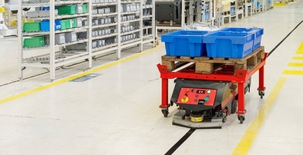
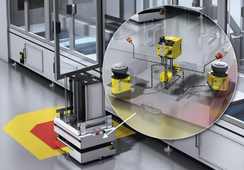
For example, the most appropriate position to completely cover an automated guided vehicle (AGV) is to have two scanners adjacent to each other on the corners integrated into the vehicle (See Figure 1).
2. Incorrect multiple sampling values configured
Multiple sampling indicates how often an object has to be scanned in succession before a safety laser scanner reacts. The out of the box default value is usually the minimum x2 scans. Although this default value can range from manufacturer to manufacturer. A higher multiple sampling value reduces the possibility that insects, weld sparks, weather (for outdoor scanners) or other particles may cause the machine to shut down.
Increasing the multiple sampling can make it possible to increase a machine’s availability, but it can also have negative effects on the application. If you increase the number of samples you are essentially adding an OFF-Delay to the system, meaning that your protective field may need to be larger due to the increase in the total response time.
If a scanner has a robust detection algorithm, then you shouldn’t have to increase this value too much but when this value is changed you could be creating a hazard due to lack of effectiveness of the protective device.
You should make a note of the safety laser scanner’s new response time if this value is changed and adjust the minimum distance from the hazardous point accordingly to ensure it remains safe.
Additionally, in vertical applications, if the multiple sampling is set too high, then it may be possible for a person to pass through the protective field without being detected. Therefore, caution must be taken. See Figure 2 for advice on the latest safety laser scanner, the microScan3.

3. Incorrect selection of safety laser scanner
The maximum protective field that a scanner can cover is an important feature, but this value alone should not be a deciding factor on whether the scanner is suitable for an application. Safety laser scanners are a Type 3 device, according to IEC 61496, and an Active Opto-Electric Protective Devices responsive to Diffuse Reflection (AOPDDR). This means that it depends on diffuse reflections off of objects. Therefore, to achieve longer ranges, scanners must be more sensitive. This means that sometimes scanning angle but certainly detection robustness can be sacrificed.
This could lead to a requirement for an increasing number multiple samples and maybe lack of angular resolution. The increased response times and lack of angle could mean that larger protective fields are required and even additional scanners — even though you bought the longer range one. A protective field should be as large as required but as small as possible.
A shorter-range scanner may be more robust than its longer-range counterpart and, as a result, keep the response time down, reduce the footprint, reduce cost and eliminate irritating false trips.
4. Incorrect resolution selected
The harmonized standard EN ISO 13855 can be used for the positioning of safeguards with respect to the approach speeds of the human body. People or body parts to be protected may not be recognized or recognized in time, if the positioning or configuration is incorrect. Safety laser scanners should be mounted so that crawling beneath, climbing over and standing behind the protective fields is impossible.
If crawling under could create a hazardous situation, then the safety laser scanner should not be mounted any higher than 300 mm. At this height a resolution of up 70 mm can be selected to ensure that it is possible to detect a human leg. Sometimes it is not possible to mount the safety laser scanner at this height. If mounted below 300 mm, then a resolution of 50 mm should be used.
It is a VERY common mistake to mount the scanner lower than 300 mm and leave the resolution on 70mm. Reducing the resolution may also reduce the maximum protective field possible on a safety laser scanner so it is important to check.
5. Ambient/environmental conditions were not considered
Scanners are electro-sensitive protective equipment and infrared light can be a complicated thing to work with. Scanners have become very robust devices over the last decade with increasingly complex detection techniques (SafeHDDM by SICK) and there are even safety laser scanners certified to work outdoors now (outdoorScan3 by SICK).
There is a big difference between safety and availability. Performance expectations need to be realistic right from the beginning. A scanner might not maintain 100% machine availability if there is heavy dust, thick steam, excessive wood chippings, or even dandelions constantly in front of the field of view. Even though the scanner will continue to be safe and react to such situations, trips due to ambient conditions may not be acceptable to a user.
For extreme environments, the following question should be asked: “What happens when the scanner is not available due to extreme conditions?” This can be especially true in outdoor application in heavy rain, snow or fog. A full assessment of the ambient conditions and even potential proof tests should be carried out.
6. Non-safe switching of field sets
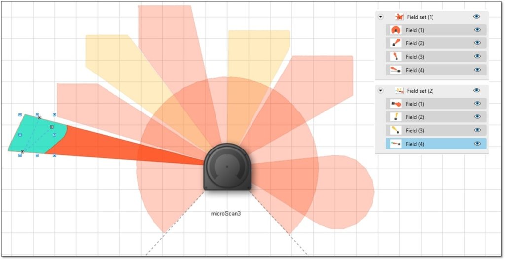
A safety laser scanner field set can consist of various different field types. For example, a field set could consist of 4 safe protection fields (Field Set 1) or it could consist of 1 safe protective field, two non-safe warning fields and a safe detection field (Field set 2). See Figure 3.
A scanner can store lots of different fields that can be selected using either hardwired inputs or safe networked inputs (CIP Safety, PROFISAFE, EFI Pro). This is a feature that industry finds very useful for both safety and productivity in Industry 4.0 applications.
However, the safety function (as per EN ISO 13849/EN 62061) for selecting the field set at any particular point in time should normally have the same safety robustness (PL/SIL) as the scanner itself. A safety laser scanner can be used in safety functions up to PLd/SIL2.
If we look at AGVs, usually two rotary encoders are used to switch between fields achieving field switching up to PLe/SIL3. There are now also safety rated rotary encoders that can be used alone to achieve field switching to PLd/SIL2.
The safety of the mode selection is sometimes overlooked. For example, if a standard PLC or a single channel limit switch is used for selecting a field set, then this would reduce the PL/SIL of the whole system to possibly PLc or even PLa. An incorrect selection of field set could mean that an AGV is operating with small protective field in combination with a high speed and hence long stopping time, creating a hazardous situation.
Summary
There are many variables to consider when designing a safety solution using scanners. Scanners are complex devices with numerous choices in the market in regards to range, connectivity, size and robustness. If you are new to this technology then it is a good idea to contact a distributor for advice on the application of these devices.
Here at A-tech we offer complimentary services to our customers such as consulting and on-site engineering assistance. We are always happy to answer any questions. If you are interested, please do not hesitate to get in touch with us.
For more information contact A-tech @ 800.225.6102